
What is the Credo Core?
The Credo Core represents the next evolutionary stage of the Credo Brake controller. True to its heritage, this controller harnesses the fundamental essence of the Credo brake controller. Dedicated to operating electric drum brakes, The Credo Core has been refined to be a cost effective solution for trailers with 1 to 3 electric braked axles. Although some features of the predecessor has been removed the multi-power sourcing architecture makes it an effective solution in a range of applications and configurations.
Credo Design Features:
- Wireless remote design with encoded link.
- Universal vehicle connection that only needs standard trailer plug wiring and no permanent vehicle brake controller wiring.
- Brake output fault detection.
- Status feedback of faults, settings, and brakes through remote control.
- Multiple power source architecture draws power from tail, brake lights and auxiliary sources simultaneously.
- A controller status LED indicator gives clear and immediate status feedback at the trailer directly on the controller.
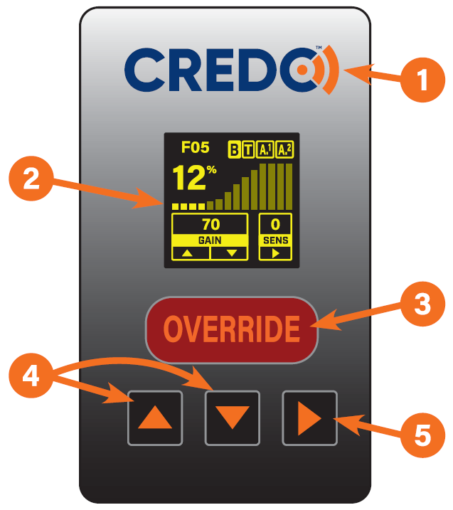
Remote Overview:
| ➊ | Connection Status Indicator:Orange LED shows connection status.
|
| ➋ | OLED Screen:Displays settings and menus for Credo operation. |
| ➌ | Over-ride Button:Override brakes engage 75% of gain. |
| ➍ | Up / Down Buttons:Used for screen navigation and adjusting setting values. |
| ➎ | Select Button:Selection button opens menu item cursor is on. |
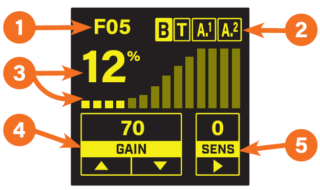
Main Screen:
| ➊ | Fault Code:Shows code for detected faults. |
| ➋ | Input Status:Displays current electrical connection status. |
| ➌ | Output Level:Current brake output level. |
| ➍ | Gain Setting:Show max brake output level. |
| ➎ | Sensitivity Setting:Adjusts the sensitivity rates in which brakes are applied. |
Remote Operation:
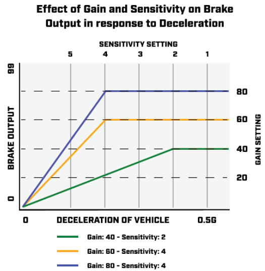
Braking Level Settings
Braking levels are adjusted with 2 settings.
Gain:
Adjust the gain to set the maximum braking output level. The minimum level is 5% and the maximum level is 99%. The level changes in steps of 5.
Adjust the sensitivity to increase the rate at which the brakes are applied. The lowest setting is 1 and the highest is 8.
Navigation
Home Screen
- Up Button: Increases gain by 5 with each press.
- Down Button: Decreases gain by 5 with each press.
- Up & down simultaneously for 5 seconds: Enter the menu screen.
- Side button: Increases the sensitivity by 1 each time it is pressed. Once the setting of 8 is reached the next press reverts the setting to 1.
Menu Screens
- Up Button: Moves the cursor up one position.
- Down Button: Moves the cursor down one position.
- Side button: Selects the menu item the cursor is on.
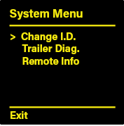
System Menu:
To enter press and hold up and down buttons at the same time for more than 5 seconds.
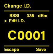
Change ID Screen:
Check the wireless signal strength and recode the ID to match the controller to connect to.
RSSI levels are shown all the time the screen is accessed and the reading is in -dBm. -0dBm is maximum signal levels and -99 dBm is the lowest. The signal typically needs to better than -80dBm.
To set the ID move the selector cursor (>) to the Edit ID entry and use the select button to select each numeral in sequence from left to right. The selected numeral has a box flashing around it. adjust the value of that numeral with the up and down buttons. The possible values of each numeral are 0-9 and then A-F in sequence.
Once finished setting the value of each numeral and there is no box flashing around any numerals use the up or down buttons to move the cursor to the Save at the bottom of the screen. Pressing select now saves the new ID into the controller. Alternatively Escape could be selected if no change is required.
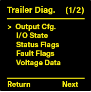
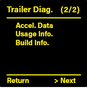
Trailer Diagnostics:
Provides access to more data in 2 pages for checking and analysing the controller status and troubleshooting.
Navigate to each page by moving the cursor to the desired page and using select to enter that page. Use select again to return the diagnostics menu.
Remote Info:
Provides manufacturers information for the remote control.
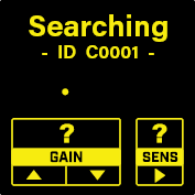
Searching Screen:
Provides the ID for the controller the remote is paired to.
Operation Guide:
| ➊ | Once trailer is hitched to the tow vehicle, coupling latched and safety equipment connected plug the trailer plug into the vehicle towing socket. |
| ➋ | Check the Controller Status light and check if the controller has powered up, if not turn the headlights on the vehicle to park or dip. |
| ➌ | In the cab of the vehicle plug in the remote to a USB socket or the supplied USB power adapter. |
| ➍ | Once the remote has started the home screen will be displayed with the current settings and controller status. If the remote shows searching instead check the serial number on the remote matches the controller on the trailer. |
| ➎ | Check the brake input status (Letter B on top bar) changes as the brake pedal is cycled on and off. |
| ➏ | Adjust braking gain and sensitivity to suit your trailer load and driving conditions. |
| ➐ | First time users can find a initial setting by adjusting the gain to a low setting of approx. 25% and then at a safe slow roll of around 5km/h press the Override to test the level of braking. The wheels should not be locking up otherwise the brakes can lock up and skid the tires while under heavy braking. |
| ➑ | Set the sensitivity to 3-4 and then do a stop from 20-30 km/h with medium pedal pressure. The braking should feel like you normally get for that pedal pressure. Experiment with higher and lower settings. Excessively high settings where the trailer is dragging the vehicle to a stop can be felt when releasing the brakes. |
24v Operation Setup:
| The Credo Core can operate with 24V vehicles but actual compatibility of the trailer with a 24V tow vehicle is determined by all the components on the trailer including lights and breakaway battery. Check the other trailer components are safe to connect to a 24V vehicle and then reduce the gain setting by approx. 30-40% from previous setting to achieve a similar braking performance. Operation with a 24V power source will require a lower setting than with 12V vehicles. However, if the brakes are used on a high setting for an extensive period of time the magnets could be damaged by overheating, This typically would mean the brakes would locked up and typically would not occur in normal service use. |
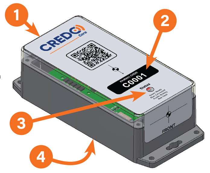
Controller Overview:
| ➊ | Aerial Location:Internally mounted aerial. Covering with metallic objects may reduce signal strength. |
||||
| ➋ | Serial Number:Program remote to match this serial when pairing. |
||||
| ➌ | Status LED:
|
||||
| ➍ | Connector:Wiring loom connector in back of controller. |
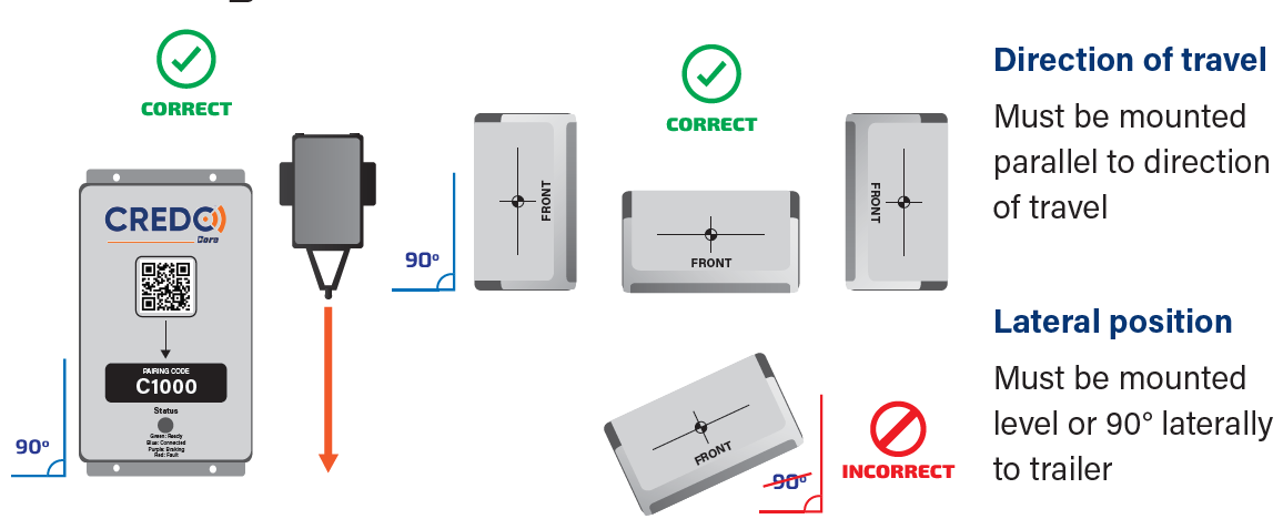
Mounting Requirements
- Must be mounted in line with the direction of travel of the trailer.
- Space for the connector needs to be allowed for.
- Mounting with the top or the sides up is possible.
- Consider visual access to the controller status LED for best user experience.
- Wireless connectivity - placing the controller inside metal enclosures or behind metal object will reduce wireless range. If additional physical protection is required place a heavy plastic cover of the controller to give protection while still allowing wireless signals to pass through. Clear acrylic or polypropylene can be used to allow the Status LED to still be visible.
Mounting Orientations
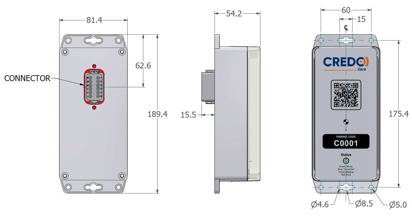
Controller Dimensions
Mounting Requirements
- Must be mounted in line with the direction of travel of the trailer.
- Space for the connector needs to be allowed for.
- Mounting with the top or the sides up is possible.
- Consider visual access to the controller status LED for best user experience.
- Wireless connectivity - placing the controller inside metal enclosures or behind metal object will reduce wireless range. If additional physical protection is required place a heavy plastic cover of the controller to give protection while still allowing wireless signals to pass through. Clear acrylic or polypropylene can be used to allow the Status LED to still be visible.
Mounting Orientations
Wiring Requirements
To ensure adequate power is available for the brakes installed on the trailer refer to the table in downloadable PDF. Make sure the brake power requirements are more than adequately met by the supplied power on the right of the table. Using auxiliary sources gives redundancy to ensure that operation is always consistent and effective even if that is more power than required.
Wiring with a junction box or direct to brakes loom is preferred for maximum reliability. Where more than 1 pin is provided for a connection connect both pins to provide full current carrying capacity.
When choosing the size of cables you use take into account the voltage drop on the cables. Using a conductor that is large enough for the current capacity is enough for small trailers but on larger trailers will cause too much voltage drop and reduce performance.
Connector Wiring Diagram
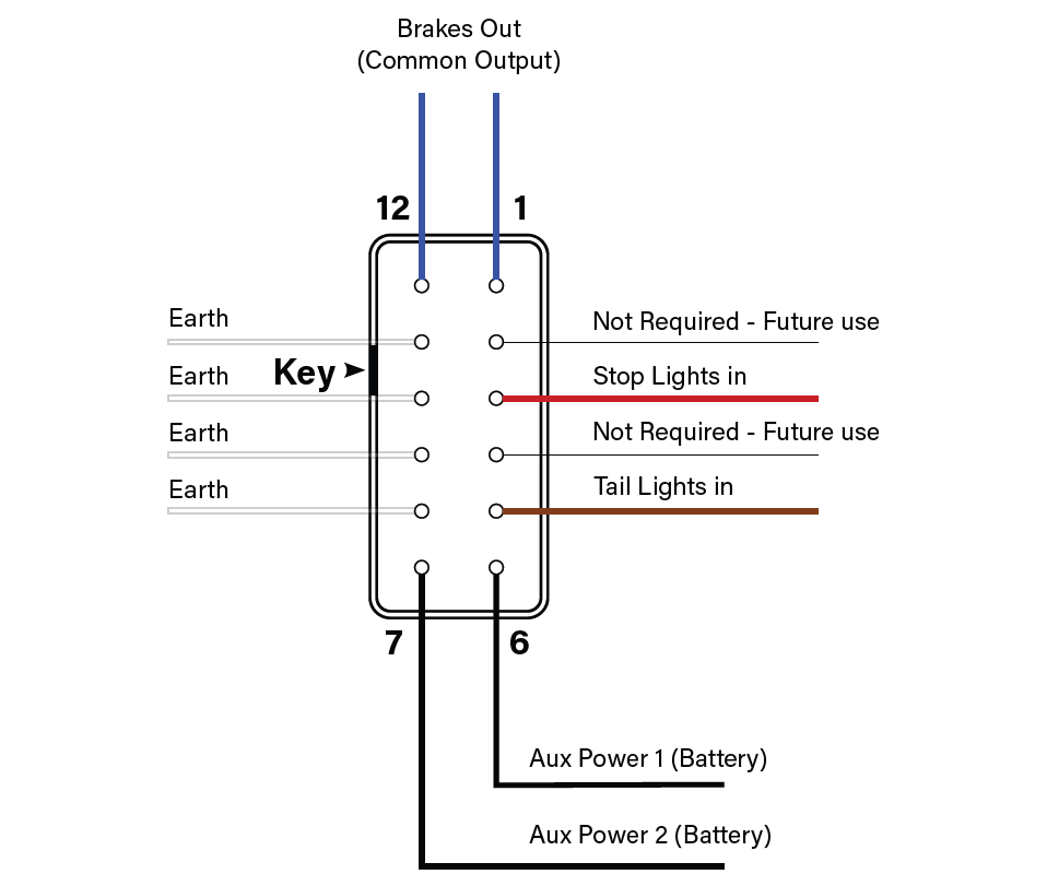
View from back of connector
Junction Box Diagram
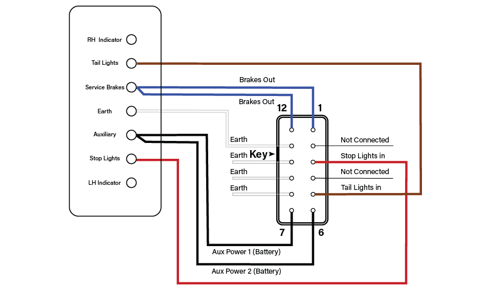
View from back of connector
7-pin Wiring Diagram
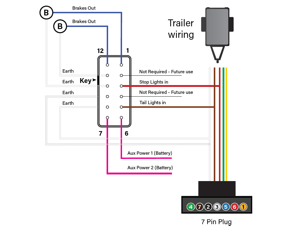
View from back of connector
7-pin Wiring Diagram

View from back of connector
Faults / Error Codes
| Fault Code | Parameter | Discription |
|---|---|---|
| F01 | Input voltage low | Controller has detected a low voltage. Check trailer plug and connections to confirm voltage on diagnostic screen. |
| F02 | Brake output - over current | Over-load detected on brake output. |
| F03 | Brake output - under current | Under-load detected on brake output. |
| F04 | Hardware failure | Controller has detected a hardware fault. Contact Trailparts for assistance. |
| F05 | Insufficient power sources available | Controller does not have enough power sources. An auxilary or tail light power source needs restoring / reconnecting. |
| F06 | EEPROM invalid | Controller has detected a memory fault. Contact Trailparts for assistance. |
| F07 | Brake output - over current | Short circuit detected on brake output (no feedback) |